Drone and UAV Technology Reviews, Articles, News, Build Logs
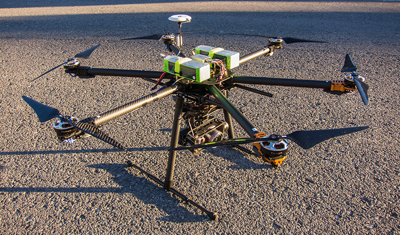
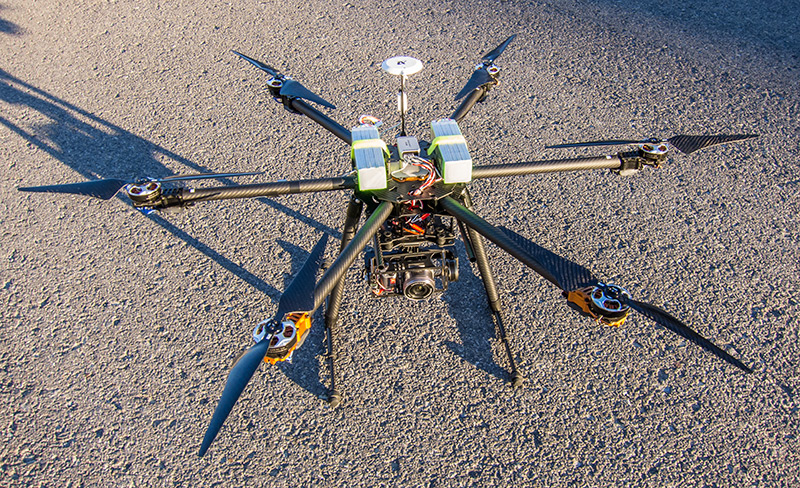
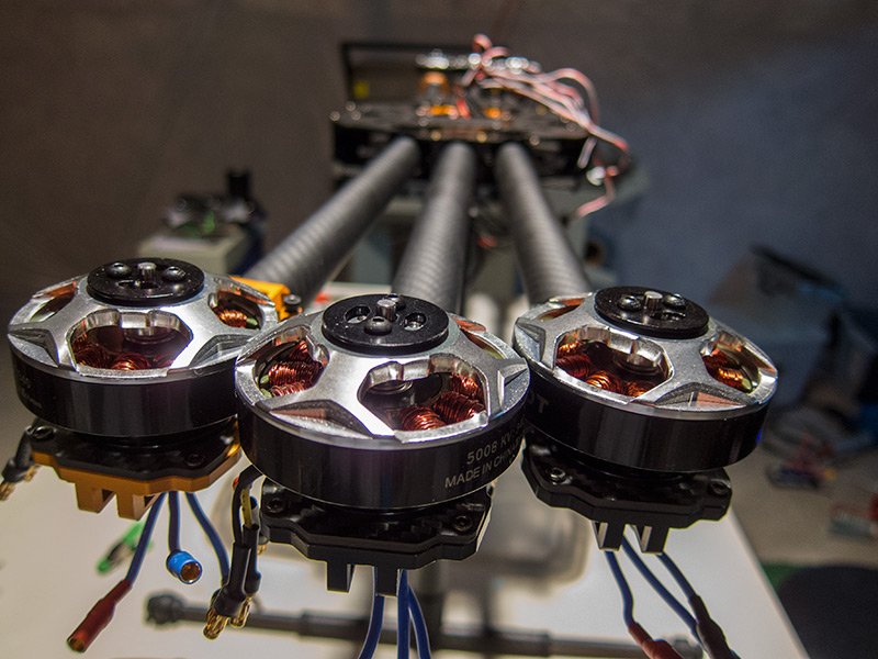
There have been a few tweaks to the hexacopter setup.
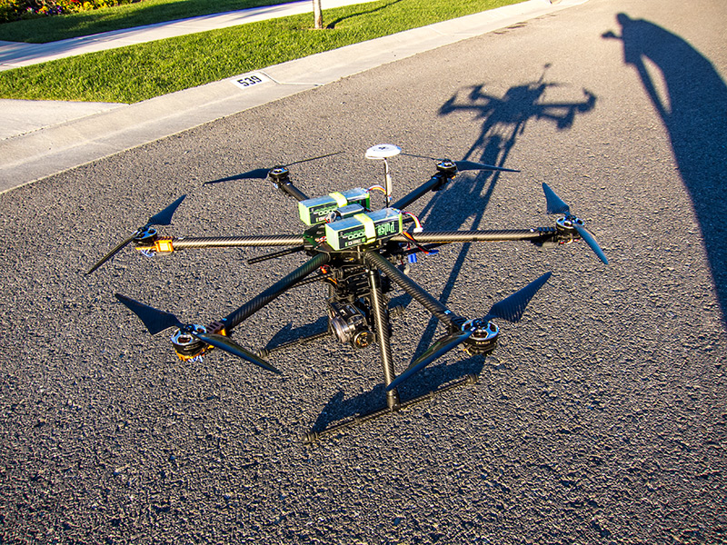
 Friday I was competing in a local golf tournament at the area’s most scenic golf course. As the tournament was to start at 10 a.m., there was an opportunity for me to get some flyover videos and photos of this great place. As the sun was coming up over the mountains and the morning dew was glistening, I found a perfect spot to launch the big hexacopter. From this spot on the 2nd tee I’d get holes 1, 2, 3, 10, and 11.
Upon power-up though, two motors beeped constantly and the SuperX flight controller LED light indicated problems. The bird was not fit to fly. I sat there looking at the absolute beautiful conditions, blue morning sky and sunrise, and NO wind. I was gutted at missing this opportunity.
My first guess was that somehow the two motors (5 and 6) needed to throttle calibrated again. Friday evening I started the calibration, but since the power was out at my house I couldn’t work too well on the bird. Over the weekend I re-calibrated the transmitter’s stick ranges, re-calibrated motors 5 and 6, and re-calibrated the compass.
The motors still beeped and the LED indicated errors.
At that point I decided to change the motor outputs and see if other motors would behave the same on the flight controller’s 5 and 6 servo leads. Sure enough, other motors would beep if plugged into 5 and 6. Conversely, plugging motors 5 and 6 into 1 and 2 servo outputs on the flight controller resulted in them booting properly and being ready to arm. That process eliminated the motors or ESC’s being the problem. The problem was the flight controller itself.
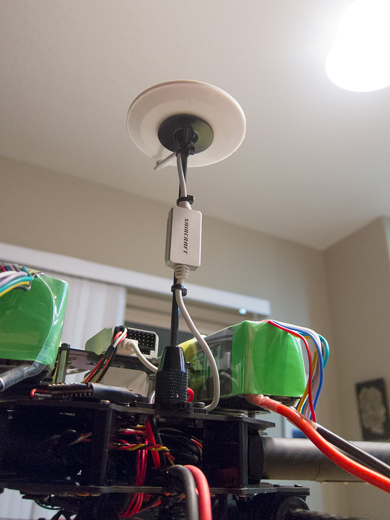
I plugged the SuperX into the computer to see if the configuration was perhaps reset to a quadcopter instead of a hexacopter. That would explain why only motors 1-4 would arm. The flight controller shows up like a hard drive on the computer when plugged in. That’s when I realized what the issue was. The software which drives the flight controller was GONE. Somehow the files were deleted or corrupted.
Simple solution, right? Reinstall the software. Not so simple. To get it, one must log in to the XAircraft website and punch in the “unit ID number” which is found…. wait for it… when you run the software! I had to send out feelers to the online community and to XAircraft for someone to send me the file SuperX.exe. It took two days, but I finally got my hands on it.
Once the files were back on the controller I was able to find my unit ID, which I’ve now saved in case something like this happens again. I successfully downloaded and installed the firmware to the controller and upon first tests, all motors were able to arm.
At that point I had to undo some of what I’d done over the weekend. I had recalibrated motors 5 and 6 with different transmitter throttle endpoints, thinking maybe something was wrong there. So I recalibrated throttle for motors 5 and 6.
I nervously took the bird out to the driveway and launched it. It drifted quite a bit and something was off. It only took a second or two of flying to realize that the yaw axis was reversed. Left was right when rotating or when banking. I had to land and reconfigure. Landing was quite challenging and nerve racking as the bird was drifting and the yaw controls were reversed. I managed to land without damage.
At that point I realized it was probably a good plan to do the ENTIRE setup/calibration over. It was the only way to make sure everything was correct. After doing that I took her for another flight. This time the bird flew solid. The yaw axis was correct and it responded as it should. I’m thinking I might go back down to 1.1 on the gains instead of 1.2. Also the gain knob somehow has been set to -33%, rather than zero. I’ll have to fix that.
Conclusion
It took three days (not 24/7 hours) of troubleshooting to diagnose and solve the problem. The copter is 95% back to where I had it prior to this issue. I’m not sure what caused the files on the flight controller to simply disappear. I’ve read that virus protection software in Windows could be a cause, but I run a Mac most of the time. However I do have to run Windows to configure the software. I theorize either some kind of static problem, or perhaps in running Windows and Mac simultaneously with the controller plugged in something was messed up.
I’ll certainly be more cautions when attaching the FC to the computer and when I’m powering it up or down.
I’ve got that other 5% of tweaks, then I can get back to finishing off my FPV setup.
I haven’t had a lot of time to work in the lab, but I have squeezed a few minutes here and there for the last few days to get the FPV (first person view) equipment setup. I chose the site getfpv.com for the gear as they came highly recommended. I already had an FPV camera, which was part of the Arris Zhaoyun 3-axis gimbal. Here’s the list of the gear from getfpv.com:
I chose 5.8GHz so those frequencies do not interfere with my remote transmitter/receiver as that is running at 2.4GHz.
Copter Side
This evening I got the basic wiring for the FPV camera on the front of the gimbal, with signal wires running from the gimbal to the 600mw A/V transmitter. I had an extra five volt JST power plug hanging from the power distribution board from some previous installations, and used that to power the FPV transmitter. Since the FPV camera is part of the gimbal, I decided to use the upper part of the gimbal as a frame to mount the transmitter and antenna.
So the gimbal attachment has the onboard big camera, FPV camera, and FPV transmitter.
Remote Side
On the receiver side I used a Phantom battery which is basically 12 volts, to power the 8″ monitor and receiver. I created and soldered a special wiring harness which has an XT60 connector for the battery on one side, and Y’s off to two power connectors for the video receiver and monitor.
Surprisingly the setup worked right off the bat (see photo below), as soon as I figured out what channel the video was being transmitted on (17).
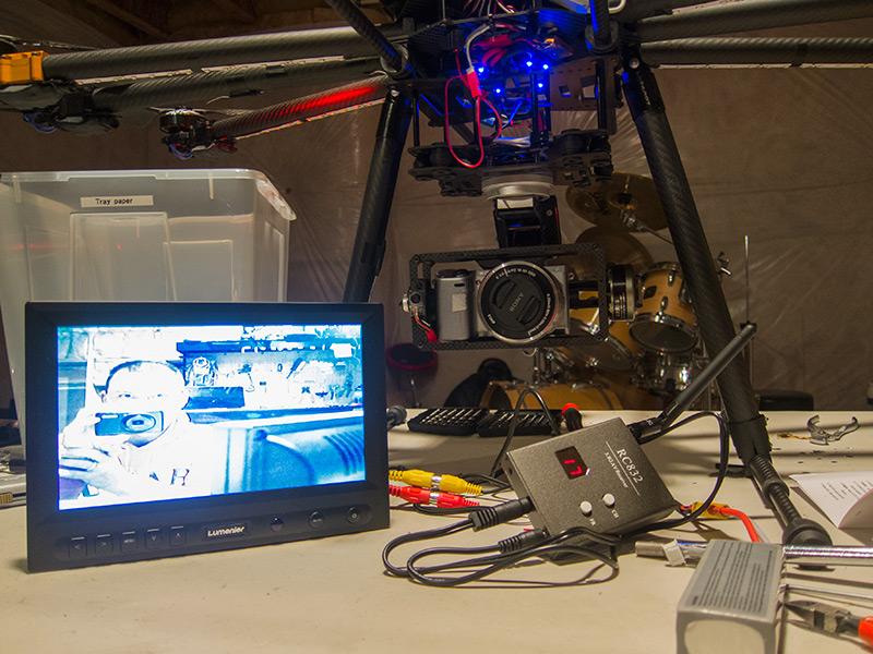
Taking a picture of the FPV camera on the copter (left of the silver Sony), and the video signal coming from it as seen on the monitor
I have yet to get the receiver, battery, and monitor attached to my transmitter. That’ll be next and then the first test flights hopefully soon.